General Description
The evaluation board demonstrates the RT9525GQW to be designed for an integrated single cell Li-ion battery charger with Auto Power Path Management(APPM). No external MOSFETs are required making it suitable for portable applications. The RT9525GQW optimizes the charging tasks by using a control algorithm including pre-charge mode, fast-charge mode and constant-voltage mode. It terminates the charging task in constant voltage mode when the charging current reduces to the termination current of 20% ICHG_FAST. The charge current is programmable with an external resister. The RT9525GQW also provides undervoltage protection and overvoltage protection for the VIN supply. In addition, the internal thermal feedback circuitry regulates the die temperature to optimize the charge rate for all ambient temperatures.
Performance Specifications
The performance specifications of the RT9525GQW are listed in Table 1. The test conditions are VIN = 5V, VBAT = 4V and TA = 25°C, unless otherwise specified.
Table 1. Performance Specifications of RT9525GQW Evaluation Board
|
Item
|
Test Conditions
|
Min
|
Typ
|
Max
|
Unit
|
|
VIN Operating Range
|
|
4.2
|
--
|
6
|
V
|
|
VIN Undervoltage Lockout
Threshold
|
|
3.1
|
3.3
|
3.5
|
V
|
|
VIN Undervoltage Lockout
Hysteresis
|
|
--
|
240
|
--
|
mV
|
|
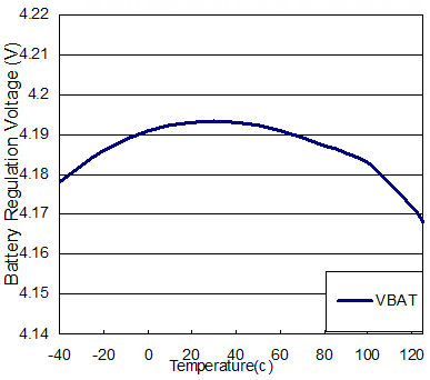
Battery Regulation Voltage
|
0°C to 85°C, ILOAD = 20mA
|
4.16
|
4.2
|
4.23
|
V
|
|
System Regulation Voltage
|
VIN = 6V
|
5.3
|
5.5
|
5.7
|
V
|
|
APPM Regulation Voltage
|
EN2 = L ,EN1 = H
|
4.2
|
4.3
|
4.4
|
V
|
|
DPM Regulation Voltage
|
EN2 = L
|
4.35
|
4.5
|
4.63
|
V
|
|
Re-Charge Threshold
|
Battery Regulation - Recharge-Level
|
120
|
200
|
280
|
mV
|
|
VIN Charge Setting Range
|
|
100
|
--
|
1200
|
mA
|
|
VIN Current Limit
|
EN2 = H, EN1 = L (1.5A mode)
|
1.2
|
1.5
|
1.8
|
A
|
|
EN2 = L, EN1 = H (500mA mode)
|
450
|
475
|
500
|
mA
|
|
EN2 = L, EN1 = L (100mA mode)
|
80
|
90
|
100
|
mA
|
|
BAT Pre-Charge Threshold
|
BAT falling
|
2.75
|
2.85
|
2.95
|
V
|
|
BAT Pre-Charge Threshold
Hysteresis
|
|
--
|
200
|
--
|
mV
|
|
Pre-Charge Current
|
VBAT = 2V
|
5
|
10
|
15
|
%
|
|
Termination Current Ratio
to Fast Charge
|
|
10
|
20
|
30
|
%
|
|
OVP SET Voltage
|
VIN rising
|
6.25
|
6.5
|
6.75
|
V
|
|
OVP Hysteresis
|
|
--
|
100
|
--
|
mV
|
|
Output Short Circuit Detection
Threshold
|
VBAT - VSYS
|
--
|
300
|
--
|
mV
|
|
Thermal Regulation
|
|
--
|
125
|
--
|
°C
|
|
Thermal Shutdown Temperature
|
|
--
|
155
|
--
|
°C
|
|
Thermal Shutdown Hysteresis
|
|
--
|
20
|
--
|
°C
|
|
Pre-Charge Fault Time
|
CTIMER = 1μF
|
1440
|
1800
|
2160
|
s
|
|
Fast-Charge Fault Time
|
CTIMER = 1μF
|
11520
|
14400
|
17280
|
s
|
Power-up Procedure
Required Equipment
- RT9525GQW evaluation board
- DC power supply
- Electronic load
- Multimeter
- Oscilloscope
Quick Start Procedures
Inspect all the components on the EVB and make sure they are undamaged. Do not turn on power supplies until they are connetced well on the EVB.
Equipment setup and the test procedures are stated below:
1) Put jumper connectors on JP1 and JP2.
2) Put jumper connectors on JP3, JP4, JP6 and JP8 at L side.
3) Put jumper connectors on JP7 at H side.
4) Adjust RV2 to 1kΩ.
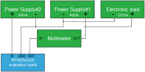
5) Set power supply #1 voltage = 4V and current = 2A and connect it to BAT through multimeter and GND pins on the EVB.
6) Connect an e-load with power supply #1 in parallel and sink 1A in CC mode.
7) Set power supply #2 voltage = 5V and current = 1A and connect it to IN and GND pins on the EVB.
8) Turn on power supply #1 and the electronic load.
9) Turn on power supply #2.
10) Check whether D1 and D2 light or not.
11) Use a multimeter to check whether IBAT equals to VISET / RISET x 300 or not.
Test Environment Diagram
Detailed Description of the Evaluation Board
Headers Description and Placement
Inspect carefully all the components used on the EVB according to the following bill of material and make sure all the components are undamaged and installed correctly. If there is any missing or damaged component, which may occur during transportation, please contact our distributors or e-mail us at evb_service@richtek.com.
Test Points
Test points are provided on the EVB and their pin names are listed in the table as shown below.
|
Test Point/
Pin Name
|
Pin Function
|
|
IN
|
Supply voltage input.
|
|
OUT
|
System connection pin.
|
|
BAT
|
Battery connection pin.
|
|
GND
|
Ground.
|
|
ISET
|
Charge current set input.
|
|
TMR
|
Safe charge timer setting.
|
|
TS
|
Thermistor monitor input.
|
|
EN1
|
Input current limit configuration setting.
|
|
EN2
|
|
SYSOFF
|
System disconnection pin.
|
|
nCE
|
Charge enable.
|
|
nCHG
|
Charger status output.
|
|
nPGOOD
|
Power good status output.
|
Bill of Material
|
Reference
|
Count
|
Part Number
|
Value
|
Description
|
Package
|
Manufacturer
|
|
U1
|
1
|
RT9525GQW
|
RT9525GQW
|
Single Cell Li-Ion Battery Charger
|
WQFN-16L 4x4
|
RICHTEK
|
|
C2
|
1
|
TMK316AB7106KL-T
|
10µF
|
Ceramic Capacitor, 25V/X7R
|
1206
|
TAIYO YUDEN
|
|
C4
|
1
|
0805X225K160CT
|
2.2µF
|
Ceramic Capacitor, 16V/X5R
|
0805
|
WALSIN
|
|
C5
|
1
|
0805B105K250CT
|
1µF
|
Ceramic Capacitor, 25V/X7R
|
0805
|
WALSIN
|
|
D1
|
1
|
LNL-191SUR
|
RED
|
LED
|
0603
|
LighTop
|
|
D2
|
1
|
LNL-190UW-4H
|
WHITE
|
LED
|
0603
|
LighTop
|
|
R2, R4
|
2
|
WR06X1501FTL
|
1.5k
|
Chip Resistor, 1/10W, 1%
|
0603
|
WALSIN
|
|
R5
|
1
|
0603X105K250CT
|
1µF
|
Ceramic Capacitor, 25V/X5R
|
0603
|
WALSIN
|
|
R6, R8
|
2
|
WR06X000 PTL
|
0
|
Chip Resistor, 1/10W, 1%
|
0603
|
WALSIN
|
|
R7, R10, R11, R13, R14
|
5
|
WR06X1002FTL
|
10k
|
Chip Resistor, 1/10W, 1%
|
0603
|
WALSIN
|
|
RV2
|
1
|
3296W103
|
10k
|
Varistor
|
3296
|
BOURNS
|
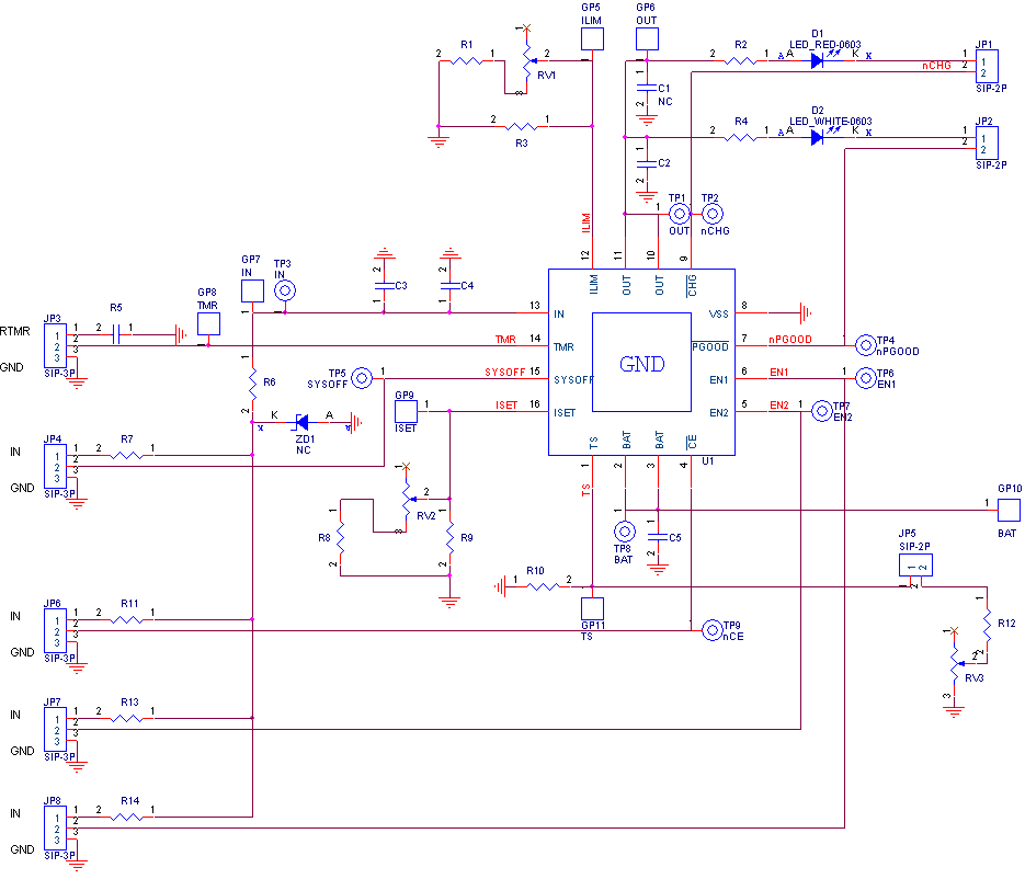
Typical Applications
EVB Schematic Diagram
Measurement Result
|
Battery Regulation Voltage vs. Temperature
|
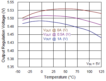
Output Regulation Voltage vs. Temperature
|
|
|
|
|
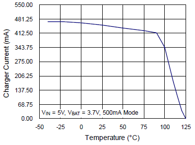
Charger Current vs. Temperature
|
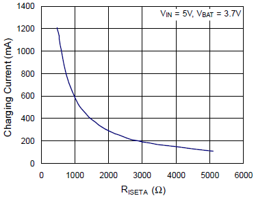
Charging Current vs. RISETA
|
|
|
|
|
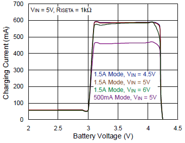
Charging Current vs. Battery Voltage
|
|
|
|
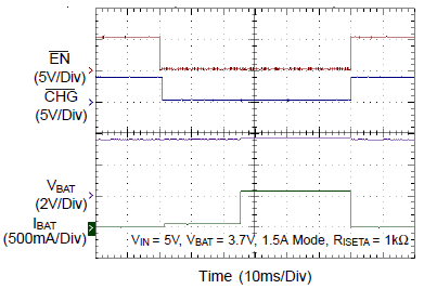
Charger Detect Sequence
|
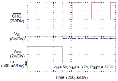
Charger /CHG Status after Safety Timer Expired
|
|
|
|
|
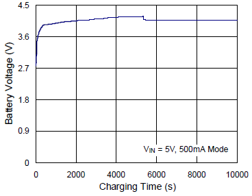
Battery Voltage vs. Charging Time
|
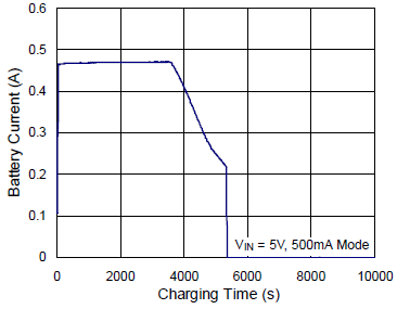
Battery Current vs. Charging Time
|
|
|
|
|
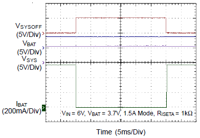
SYSOFF On/Off with Input Power
|
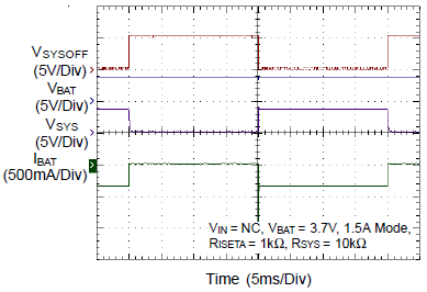
SYSOFF On/Off without Input Power
|
|
|
|
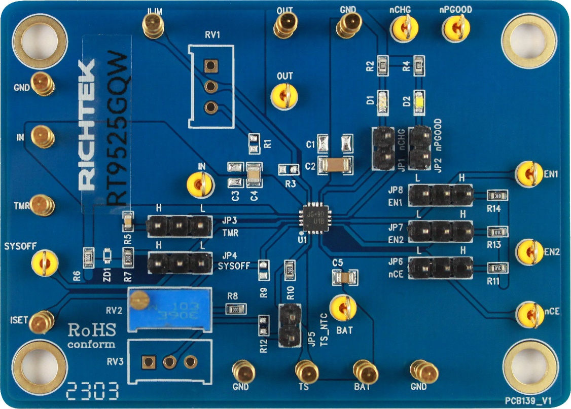
Layout of the Evaluation Board
The layout of RT9525GQW evaluation board is shown in Figure 1 and Figure 2. It is a two-layer PCB with 1 oz. Cu coated on both top and bottom sides and the PCB size is 70mm x 50mm.
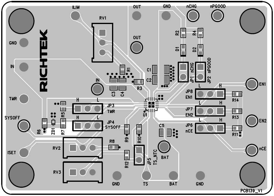
Figure 1. Top View (1st layer)
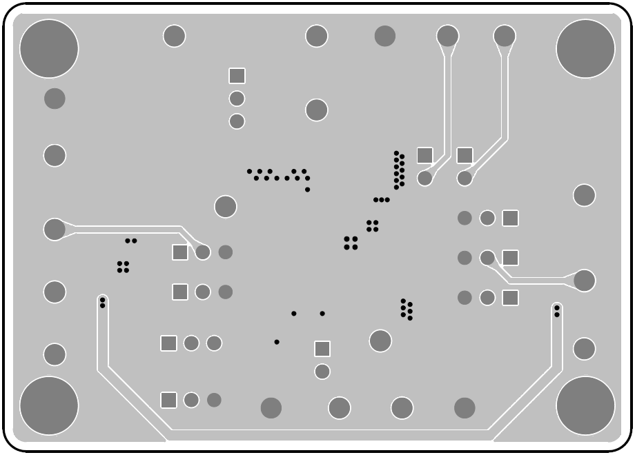
Figure 2. Bottom View (2nd layer)